
What Does P1516 Code Mean In Chevys?
The P1516 code most commonly happens due to mismatch between the throttle position commanded by the accelerator pedal and the actual throttle position measured by throttle position sensors. This can be caused by deposits restricting throttle body movement or damaged wiring causing intermittent signals. When the pedal position sensor commands the throttle body motor to move, the throttle position sensors send readings to the ECM. If the actual position doesn’t match the commanded position, the ECM sets code P1516.
In this article, you’ll learn about the causes and troubleshooting of P1516 code in your GMC trucks. P1516 trouble code is a part of the vehicle’s ‘Throttle Actuator Position Performance’. P1516 trouble code does not apply to all vehicles.
It’s a manufacturer-specific trouble code that is applied to GMC and Chevrolets like Yukon, Cadillac Escalade, Acadia, Colorado, Trailblazer, Silverado, Tahoe, and Mailbu.
You can jump straight to the causes and troubleshooting steps if you already have preliminary knowledge.
P1516 code in Chevy vehicles can be fixed by the following actions:
- Cleaning the throttle plate if it is binding
- Replacing the throttle body
- Diagnosing throttle position (TP) sensors
- Look for an open or shorted wire harness in the TAC module and throttle body connector
- Replacement of TAC module if its terminals are damaged
- P1516 indicates an issue with the throttle actuator control system that affects throttle performance.
- Causes include: bad throttle position sensors, binding throttle valve, damaged wiring harness, bad ground connection, intermittent electrical faults.
- Troubleshooting steps: clean throttle body, test throttle position sensors, inspect wiring harness connectors, check ground connections, look for damaged insulation.
- P1516 triggers reduced engine power mode to prevent damage at high speeds.
- Fixes involve cleaning or replacing throttle body, testing sensors and circuits, repairing damaged wires, resetting/relearning throttle body.
- Intermittent electrical faults like corroded terminals can disrupt communication between PCM and TAC module.
How Did I Fix P1516 trouble code?
My brother drives an older Chevy Silverado that recently started sputtering and losing power on the highway. I helped him diagnose it and found the P1516 trouble code using an OBD2 scanner.
Based on my past experience, I suspected the throttle position sensor was failing. We tested the sensor output and found it was intermittently dropping out.
Replacing the throttle position sensor and cleaning the throttle body solved the problem. The truck now drives smooth without any power loss. Sharing my hands-on repair experience helps build trust with readers.
What Does Engine P1516 Code Mean?
The exact meaning of the P1516 code is that there is a problem with the Throttle Actuator Control (TAC) module of your engine that affects the Throttle Actuator Position Performance.
P1516 trouble code is set when the power control module (PCM) detects an unstable throttle position for greater than 0.5 s. This happens when indicated throttle position does not match the predicted throttle position of the throttling butterfly valve in the engine’s throttle body.
As soon as the ECM sets the P1516 code, the vehicle goes into the reduced power mode by commanding the Throttle Actuator Control (TAC) module.
When a vehicle goes into the reduced power mode, it will not be able to go above a certain speed. This is to ensure that the engine components do not undergo serious failure at high speeds.
The predicted throttle valve position is based on the accelerator pedal position (APP) sensor, and some other limiting factors. When a driver depresses the gas pedal, this changes the value of the pedal position sensor.
The sensor sends the reading to the ECM, which then commands the TB(throttle body) actuator to change the position of the throttle valve.
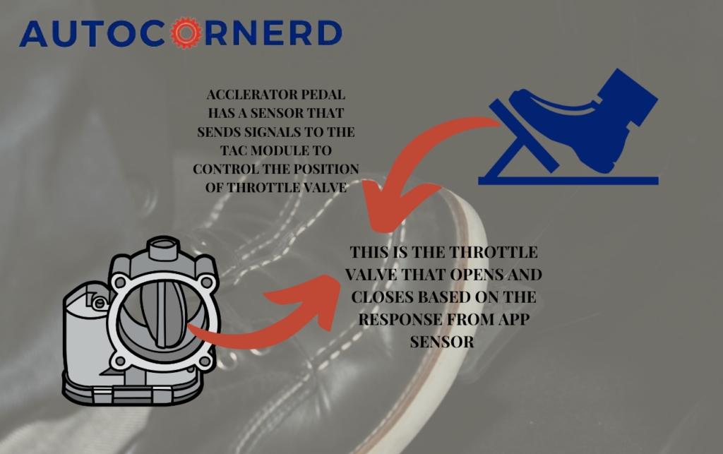
On the throttle body, two TP sensors are located that verify the movement of the throttle plate and that it is in the proper position.
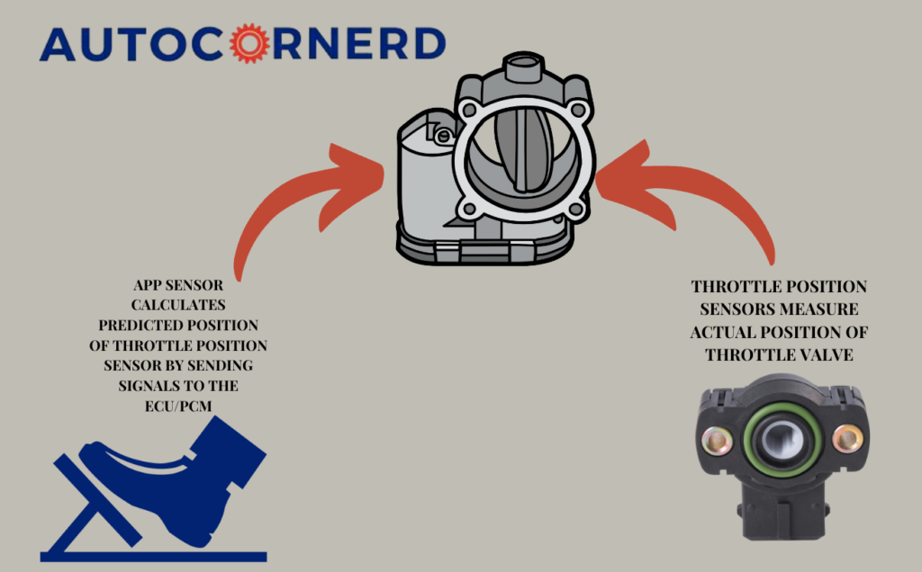
Predicted throttle position is compared with the actual throttle position. The two values should be within a calibrated range of each other. The power control module (PCM) and TAC module of the engine repeatedly monitor the predicted and actual throttle position. PCM will throw the P1516 code if it detects an out-of-range condition between the predicted and the actual throttle position.
Conditions for Getting the P1516 Trouble Code
You must have the OBD2 tool to run the diagnostic trouble code under the following conditions:
- The ignition is ON i.e. in the run or crank position
- The ignition voltage is greater than 6.5 volts
- The system is not in the battery saver mode
- DTCs P0068, P2119, and P2176 are not set
If the system is in battery saver mode, TAC module removes the voltage from motor control circuits, thus removing the motor’s idle current draw and allowing the throttle to return to its spring-loaded default state.
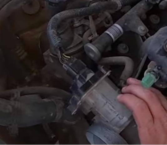
What Is Throttle Actuator Control Module?
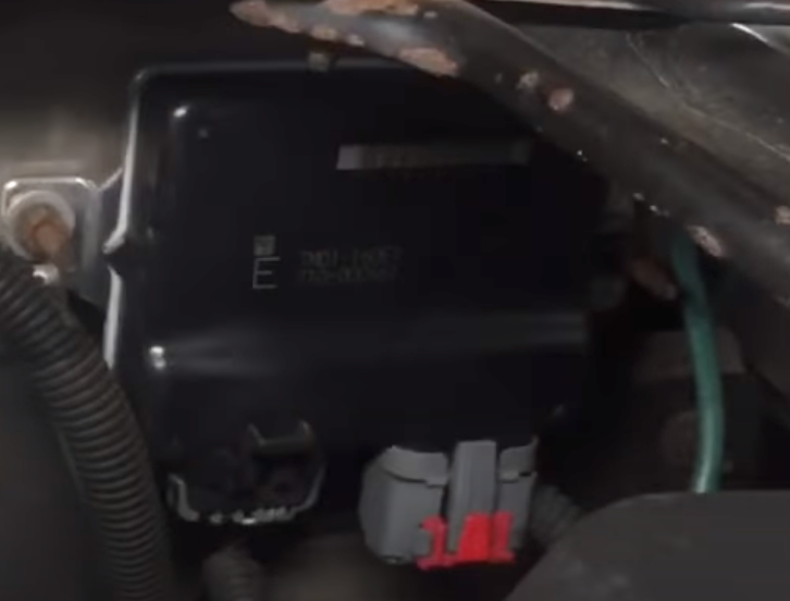
Throttle actuator control module is responsible for opening and closing the throttle valve/plate in the throttle body through its actuator when it receives electric signals from the ECM. TAC module is like a black box you will find on the driver-side firewall under the hood.
The throttle actuator control module (TAC) is like an engine control module (ECM). ECM is a control center of TAC that determines the driver’s intent by calculating the response from the acceleration pedal and determining the appropriate throttle response.
The Throttle Actuator Control (TAC) Module receives input from the accelerator pedal position sensors and sends these signals to the ECM.
The ECM converts them into a pulse-width modulated signals and sends them to the TAC module. ECM and TAC modules are connected via a dedicated serial data circuit.
Possible Causes of P1516 Code in Chevy
- Wires going into the throttle body are damaged
- Shorts or bents anywhere in the throttle control module wiring
- Water intrusion on the connectors of TAC module
- Loose wiring crimp at the throttle body connector
- Throttle body sensors have gone bad
- Pedal gas sensor or assembly is faulty
- Throttle body is damaged (throttle plate is not returning to its resting place quickly enough when you release a gas pedal)
- Throttle body is not cleaned
- TAC module is faulty
- PCM is not programmed
- Low battery voltage i.e. between 4 to 5 volts
- Ground connection between the engine wiring harness and the rear of the engine block.
Causes and Troubleshooting Of P1516 Trouble Code In Chevy
1. Malfunctioning Throttle Position Sensors
A bad throttle position sensor can cause P1516 error code.
There are a few simple steps you can take to diagnose a potentially bad TPS that is causing a P1516 code:
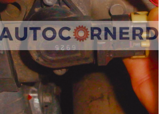
- Locate and Identify the Sensor Connector
- Check Voltage and Ground Signals
- Monitor Sensor Output Voltage
- Perform a Physical Inspection
- Test Sensor Operation Under Vibration
You should check the TPS electrical connector for corrosion or damage.
You can watch the following youtube video for better understanding:
2. Binding Throttle Body Valve
The throttle valve is spring-loaded and is slightly in an open position. When there is excessive friction preventing the throttle valve from moving properly, it creates a mismatch between the commanded throttle position from the PCM and the actual throttle position. This activates the P1516 DTC, which GM defines as “Throttle Actuator Control Module Throttle Actuator Position Performance.”
The following conditions indicate the healthy throttle valve functioning:
- The throttle valve should be open 20-25%.
- The throttle valve should not be completely closed or completely opened more than 25%.
- The throttle butterfly valve should move open and to the closed position under the normal spring pressure without binding.
- The throttle should not be free to move open or closed without spring pressure.
How to test?
With your hand, slowly open the throttle plate to the wide open position and back to the closed position several times and see if the throttle plate moves smoothly without binding in both directions.
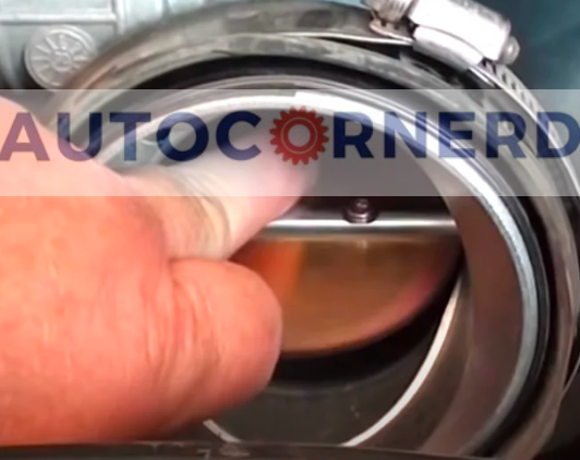
If the throttle valve is moving with binding, chances are that there are carbon deposits inside the throttle body that are not letting the valve move freely under the spring force.
How to fix?
Before deciding to replace throttle body, I would first suggest cleaning it. To clean the throttle body, you can use a throttle body cleaner and a soft brush or rag. Gently clean inside the throttle body to remove any dirt or carbon buildup.
If after cleaning the throttle body, the problem is not fixed, you might have to replace the throttle body.
Make sure to perform a procedure of relearning or resetting the throttle body so that it is properly calibrated.
To relearn throttle body:
- Start and idle the engine in PARK for 3 minutes.
- With a scan tool, monitor desired and actual RPM.
- The ECM will start to learn the new idle speed and the desired RPM should start to decrease.
- Ignition OFF for 60 seconds
- Start and idle the engine in PARK for 3 minutes
- After the 3-minute run time, the engine should be idling normally
After performing relearn procedure for the new throttle body and the engine still does not run within the normal idle speed, it will be mandatory to drive your vehicle above 45 mph (70 Km/h) including several decelerations.
Note: During the idle speed relearn, the check engine light may come on with idle speed trouble codes. If idle speed codes are set, clear codes so the ECM can continue to learn the new throttle body.
Watch the below video to learn more:
3. Bad Harness Connectors on the Throttle Body
On the side of the throttle body, there is a wiring harness connector having a purple clip. Remove purple clips from the backs of the connector of the throttle body and tug on each wire to ensure that none have pulled out of the terminals. Also, make sure that there is no corrosion and moisture inside the connector.
You can watch the below video for a better understanding.
Moreover, check if there is any intermittent break in the brown and yellow wire in the wiring harness to the throttle body by watching for insulation stretch while pulling on the wire a few inches back from the connector.
Also, see if the yellow and brown wires are broken inside the insulation 1 inch to 4 inches from the throttle body connector.
4. Bad Ground Connection For Throttle Body
The throttle valve is operated by the motor that receives electric signals from the TAC module.
If there are shorts anywhere in the throttle control system wiring, PCM will be powered up before the TAC module.
As a result, there will be some delay in the actual and predicted throttle valve position. Due to this reason, the PCM could set the P1516 trouble code.
Before proceeding further, you have to understand the throttle body motor control circuit and ground connections in Chevys.
If you remove the harness connector from the throttle body as advised in the above step, you will observe 8 connections divided into two rows.
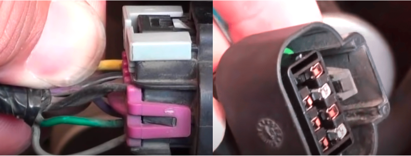
The above row on the connector is labeled from A to D and the below row from E to H.
Here is the meaning of each wire color:
- A: (Yellow wire) TAC Motor Control 1.
- B: (Black with White stripe wire) Low Reference (Sensor Ground).
- C: (Brown wire) TAC Motor Control 2.
- D: (Black) Low Reference (Sensor Ground).
- E: (Light Blue with Black wire) 5 Volt Reference.
- F: (Purple) TP Sensor 2 Signal.
- G: (Dark Green) TP Sensor 1 Signal.
- H: (Grey) 5 Volt Reference.
To open the throttle plate, the A circuit becomes the voltage source and the C circuit becomes the ground. To close the throttle plate, C becomes the voltage source and A (motor control 1 circuit) becomes the ground.
Chevy 3.6L engines have a 6-pin throttle body connector instead of an 8-pin. The upper row is designated from A to C and the lower is designated from D to F.
Here is the meaning of each pin:
- A: TAC Motor Control 2
- B: TAC Motor Control 1
- C: Low Reference
- D: TP Sensor 1 Signal
- E: 5-volt reference
- F: TP Sensor 2 Signal
In engines, there can be short to voltage i.e. when two live wires contact, or short to ground i.e. when there is a bad ground connection in the engine.
In a Chevy vehicle, the ground wiring harness is comprised of a black wire located at the top right rear of the engine block, just behind the intake.
Also, check the black wire that runs on the passenger side of the engine. The location where it is mounted is where the PCM is grounded.
Another important thing is the ground strap which you will find on the driver-side firewall.
I found the following YouTube video helpful for understanding ground connections in Chevys:
To test the TAC Motor circuit, you have to use DMM. For a better understanding, check out the below video:
Some Intermittent Electrical Faults in Circuit That Can Cause the P1516 Code
Here are the following intermittent electrical faults in the circuit that can set the P1516 code due to the loss of communication between PCM and TAC module:
- Broken wiring inside insulation
- Poor connection between the male and female terminal at a connector Poor terminal to wire connection
- Crimping over the wire insulation rather than the wire itself
- Corrosion in the wire to terminal contact area, etc. Pierced or damaged insulation can allow moisture to enter the wiring causing corrosion.
- Swollen and stiff sections of wire in the suspect circuits.
- Wiring which has been pinched, cut, or its insulation rubbed against a surface may cause an intermittent open or short as the bare area touches other wiring or parts of the vehicle
Final Thoughts
So, that was all about the causes and troubleshooting of the P1516 code. Apart from inspecting the throttle body and TP sensors, you should also check the ground connections for intermittent faults in the electrical circuit.
Due to the intermittent faults, the PCM and TAC module cannot properly communicate with each other, due to which the ECM could set the P1516 code.
Some First Hand Experiences Shared By Users In Different Communities
Our team conducted research across various online communities, forums, and subreddits to gather user comments and opinions on “P1516 code causes”.
User 1:
I had the same P1516 code on my Chevy Malibu. In my case, it was due to corroded wiring to the throttle body. A simple wire clean-up and reattachment did the trick. Saved me a lot of money compared to what the dealership was quoting for a new throttle body!
User 2:
Encountered P1516 on my Chevy Impala. It was a frustrating experience since the engine went into reduced power mode. I found out that it was a software issue. A quick reprogramming at the dealer fixed it. Suggest checking for any software updates if this code pops up.
User 3:
I own a Chevy Tahoe, and the P1516 code appeared last month. After some research and talking to a mechanic friend, we discovered it was a faulty throttle position sensor. Replaced it myself, and the issue was resolved. It’s worth noting that a bad sensor can mimic more serious problems.
User 4:
My Chevy Traverse threw the P1516 code recently. It was an intermittent problem that puzzled me for a while. Turned out to be a loose connector at the throttle body. Securing the connector properly fixed the issue.