
4 Bad Ignition Control Module Symptoms (ICM)
The main symptoms of a faulty ignition control module (ICM) include difficulty firing up the engine or complete failure to start it, reduced gas mileage paired with deficient engine power, misfiring of engine resulting in the check engine illuminating, and fluctuation of engine’s RPM at high speeds. Explicit diagnostic trouble codes indicating potential ICM breakdown are P0300 (general engine misfire) and cylinder-explicit codes such as P0301 through P0304. Other affiliated issues could originate from complications with the fuel injectors, fuel pump, spark plug cables, vacuum leaks, or wiring harness.
Note: Below, I have also explained the proper working of ignition module and its types. This will help in troubleshooting the root cause. If you have preliminary knowledge, you can jump straight to the section on bad ignition control module symptoms.
What Exactly Is Ignition Control Module?
The Ignition Control Module (ICM) regulates timing and firing of spark plugs in vehicles. Located in various places like inside the distributor or near the firewall, its purpose is ensuring smooth, efficient engine operation.
The ICM works by processing signals from sensors like the crankshaft position sensor. It uses this input to determine the correct timing for igniting the air-fuel mixture via the spark plugs.
This occurs continually as the engine runs, controlling dwell time – the duration current flows through the ignition coil before discharging to create a spark.
Essentially, the ICM oversees current flow to the ignition coil’s primary winding, which is then transformed into thousands of volts to ignite combustion in the engine.
So by controlling spark plug firing, it enables precision-timed explosions in each cylinder for optimal engine performance.
The ICM is thus an critical electronic regulator in the ignition system. Receiving sensor data and responding with timing signals, it conducts an orchestra of controlled combustion under the hood.
Bad Ignition Control Module Symptoms (Detailed Explanation)
1. Difficulty Starting From Faulty Ignition Control Unit
A failing ignition control module (ICM) often manifests in difficulty starting your car or complete failure to start. This critical component coordinates spark plug firing so fuel ignites properly.
When the ICM malfunctions, sparks fail to ignite the fuel-air mix in your engine. Without combustion, the engine struggles to crank or even turn over.
2. Poor Performance and Mileage From Defective Control Unit
An underperforming ICM hampers more than just starts. Expect decreased power with sluggish acceleration along with reduced fuel economy. Why the wide-ranging impact?
Faulty ignition timing prevents proper firing in all cylinders. Unburned fuel diminishes output while wasting gas.
3. Rough Running and Misfires Trigger Check Engine Light
Erratic cylinder firing caused by ICM troubles frequently activates the check engine warning. Misfires occur when fuel ignition mistimes, causing choppy operation, hesitation, even stalling. This stresses other components like the catalytic converter.
At highway speeds, fluctuating RPMs signal issues. The powertrain control module detects misfires, triggering error codes that pinpoint failing cylinders.
For example, P0300 indicates general misfires while P0301 through P0304 denote specific cylinders. diagnose and repair ignition problems promptly to avoid unnecessary damage.
If you don’t have idea about engine cylinder numbers, you can read this guide.
4. Fuel Odor Caused By Ignition Control Module Malfunction
If the ICM deteriorates further, it may cause retarded ignition timing. Retarded ignition timing is when the spark plug fires later than the ideal timing. This reduces combustion efficiency, resulting in unburnt fuel exiting via the exhaust.
This is evident from a distinctly pungent odor of unburnt fuel emanating from the tailpipe.
During normal operation, combustion is designed to finish just as the exhaust valve opens. This ensures most of the fuel vaporizes and burns.
Retarded timing means the air-fuel mixture does not get sufficient time to fully combust. Partially burnt fuel vapor exits into the exhaust system, giving rise to a gasoline-like smell.
The exhaust gases contain hydrocarbons from the unburnt fuel. When these hot gases pass through the catalytic converter, the hydrocarbons briefly get oxidized before exiting via the tailpipe. This oxidation generates a range of smelly compounds.
A noticeable fuel smell is very unlikely to stem from bad ICM-induced retarded timing alone. Most common causes are:
- Leaky fuel injectors, allowing raw fuel into the cylinders
- Rich air-fuel mixture due to faulty oxygen sensors or fuel pressure regulator
- Coolant getting mixed into combustion chambers due to a blown head gasket
- Worn piston rings unable to seal compression, allowing oil and unburnt fuel vapor entry past the rings
Other Causes That Can Result In Car Starting and Stalling Issues
If you checked the ignition control module and distributor, but couldn’t fix the issue, I would highly recommend you check fuel injectors, fuel pump, spark plug cables, vacuum leaks, EGR valve, knock sensor, fuel filter and cam phaser. In addition, you should check the ground connections of the ECM.
Furthermore, connections on engine’s computer are very sensitive, meaning that even a small wiring issue can cause a significant problem. One person was facing vehicle no starting issues that had 350 TBI engine. He found that harness that connected to the distributor had been removed from the retainer, which likely caused some electrical signals to be lost or disrupted. This caused the car to not run or idle as it should have. The person reconnected (tightened) the connector pins that were connected to the ignition module. They then placed the harness back into the retainer, which secured it in place and allowed all electrical signals to flow as they should have.
How Does Ignition Control Module Go Bad?
Here are the factors due to which an ignition control module can go bad:
1. Heat Damage Shortens Component Life
The ignition module’s location next to hot engine components subjects internal electronics to elevated temperatures over long periods. This thermal stress takes a toll over time.
Electrical components and connections expand and contract with temperature swings. Materials eventually fatigue and fail to function properly. Heat also accelerates the breakdown of insulating compounds and solders over years of exposure.
2. Moisture Corrosion Degrades Internal Circuitry
Water is electronics’ mortal enemy. And residing in an open engine compartment makes modules vulnerable.
Condensation, pinhole wire insulation cracks, leaking gaskets and seals – all provide pathways for moisture ingress. Once inside, water causes internal shorts and corrosion that disable electronic circuitry over months or years.
3. Constant Vibrations Take Their Toll
The module’s home next to the engine subjects it to endless high-frequency vibrations from engine operation and road impacts. Years of bombardment can fracture solder joints or cause components to shift from their mounts.
In distributor-type systems, worn shaft bushings allow sideways shaft movement. This misaligns timing signals to the module, resulting in spark scatter.
4. Voltage Spikes Disrupt Circuit Operation
Stable voltage and clean grounds are critical for proper module function. But faults in charging or electrical systems can unleash voltage spikes reaching multiples of battery voltage. These brief events pack lots of energy to damage sensitive electronics.
Common causes are overcharged batteries, alternator failures, or poor wiring condition allowing shorts. Spikes overload and puncture semiconductors or blow protective devices leading to partial or complete circuit failure.
5. Distributor Pickup Malfunction Affects Ignition Timing
In contactless distributors, the bushing area gets worn out which causes the shaft to move sideways.
This sideways movement leads to the reluctor points on the shaft striking the points on the pickup coil pole piece. When this happens, the ECM is unable to receive a proper signal for RPM and timing, leading to timing issues and eventually engine misfires.
More on distributor pickup coil working is explained in the next section.
6. Damaged Wire Insulation Causes Shorts
Environment hazards that reach module internals also attack connected wiring. Years of heat, moisture, oil exposure and vibration wear away protective insulation allowing conductors to contact each other or other components.
Resulting short circuits divert current causing erroneous signals or module damage.
7. Loss of Magnetism Alters Performance
In distributor systems, the magnet induces critical voltage in pickup coils signaling module timing and speed controls. But constant heat exposure can demagnetize components over time.
Weakened magnetic fields generate low voltage failing to trigger module properly. This leads to spark scatter or shutdown.
Ignition Control Module Variations
The early ignition control modules were once elementary on/off switches activated by magnetic pulses from the distributor. The distributor houses a spinning reluctor wheel and stationary pick-up coil.
The reluctor has evenly spaced teeth matching the engine’s cylinders. As it spins on the distributor shaft, the teeth pass the coil and its permanent magnet.
Fluctuations in the magnetic field around the coil generate electrical pulses. The pulses trigger the module to fire the ignition coil, much like an on/off switch.
Upgrades now precisely time and sequence ignition events. But originally, magnetic pick-ups turned simple control modules on and off. The distributor converts mechanical motion into electric signals to fire the spark plugs. The number of reluctor teeth equals the number of cylinders, ensuring properly timed sparks.
If you want to know about the difference between contactless and electronic distributors, you can watch the following YouTube video:
Later on, computerized engine controls were made and the ignition module’s design was changed.
The new design of ignition control module had a square-wave signal sent to the engine control module (ECM), after which the ECM would calculate how much spark advance was needed for the engine operating conditions. The ECM then sent a square-wave signal back to the ignition module to trigger the spark to start the engine.
As operations become more complex, the module is often moved from the inside of the distributor to cooler locations like an engine compartment fender well.
In more late-model instances, the ignition module is integrated into the powertrain control module (PCM), also called ECU, itself to simplify system electronics.
Here is a simpler arrow diagram of how ignition control modules transformed with time:
Ignition Timing In Electronic Distributor Modules
The mechanical advance device in an electronic distributor progresses the firing timing as the engine’s RPM rises. The mechanical advance’s role is to calibrate the ignition timing in line with the piston’s location inside the cylinder.
Within a mechanical advance framework, there exist two key pieces:
- Flyweights
- Spring
The flyweights connect to the distributor shaft and whirl as the motor speeds up. As the flyweights spin, centrifugal force thrusts them outwards. This movement squeezes the spring, which then pushes back against this motion, forming a balanced effect.
The flyweights’ movement rotates the trigger mechanism (reluctor wheel on distributor shaft), advancing the ignition timing.
The spring’s tension dictates the rate of mechanical advance. Various springs can generate different advance rates. A stiffer spring will need higher engine rotations to overcome its pushback and start the advance, resulting in a delayed timing advance.
The vacuum advance component in an electronic distributor calibrates the ignition timing based on the engine’s vacuum. The vacuum advance consists of a diaphragm, a spring, and a vacuum chamber. The vacuum chamber links to the air intake manifold via a hose, while the spring holds the diaphragm in a neutral spot.
When operating, the engine’s vacuum pulls the diaphragm, which then rotates the distributor shaft, moving the timing forward.
Key Point: The mechanical and vacuum advance systems co-operate to deliver optimal timing for the spark. At low engine speeds, the vacuum advance system handles advancing the spark timing. As engine RPMs climb, the mechanical advance system takes over, further advancing the ignition timing. This combined system enables precise spark timing throughout the entire range of engine speeds.
Spark Advance In 350 TBI Engines
350 TBI engines also have ignition control module inside the distributor. But, it has no role when the engine is running at higher RPMs.
The 350 TBI engines have an EST (Electronic Spark Timing) ignition system. The distributor of the EST ignition system in 350 TBI engines does not have mechanical or vacuum advance.
In EST electronic distributors, an electric spark timing module is mounted in the distributors that receives signals from the engine control module (ECM) to advance the ignition timing.
So, in these systems, all spark timing changes are controlled electronically. In simple words, EST is the advanced version of the ignition control module.
Many people also confuse ESC with ETC. ESC (Electronic Spark Control) is something else. It is not inside the distributor. The ESC only signals the ECM to retard the ignition timing (which the ECM signals to the EST in turn). It pulls out the ignition timing to get rid of the knocking.
In some models, the ESC module lies on the bracket along with the EGR solenoid, the passenger side of the TBI. The module is mostly flat.
In some vehicles, the ESC module is mounted on the firewall directly behind the air cleaner. You will still find that bracket with the space for the ESC but it would be blank other than the EGR solenoid. In later models after 1993, ESC module has been integrated into the ECM.
How To Diagnose and Test A Bad Ignition Control Module?
To diagnose and test a bad Ignition Control Module (ICM), you can follow these steps:
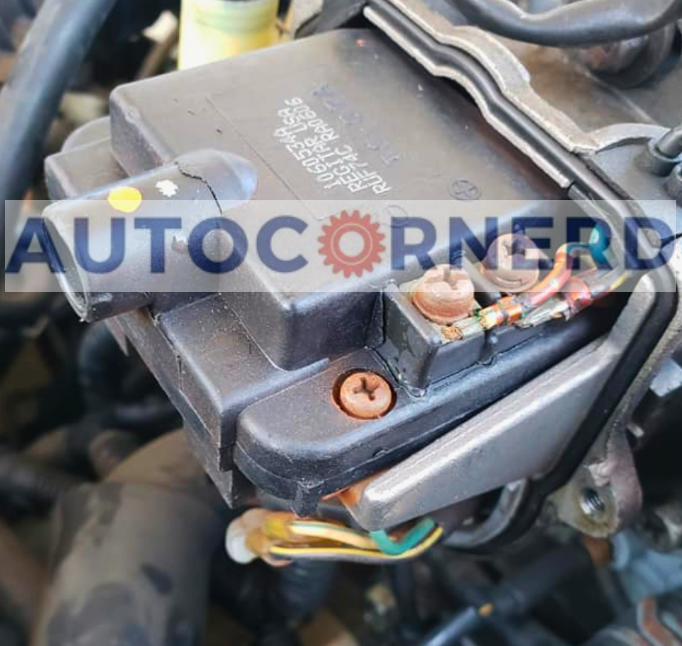
- Visual Inspection: Check for any visible signs of damage or corrosion on the ICM.
- Multimeter Test: Use a multimeter to test the ICM. With the key in the “On” position, measure the voltage between the positive and negative leads of the output plug on the module. It should read around 12V.
- Checking connections and wires: Before replacing any parts, it’s a good idea to check for loose connections or damaged wires.
- Ground Contact: Clean and sand the ground contact between the ICM case and the body/frame.
Replacement Cost Of A Bad Ignition Control Module (ICM)
The cost of replacing an ignition control module (ICM) can vary depending on the vehicle and where the replacement is done. Here are some examples from different forums:
- On a Chevy S-10, a dealership replaced the failed ignition coil and the ignition control module, which was a $400 part. (Source 1)
- For a 1994 Sonoma, the part cost about $120, and a user bought an ignition module for about $40 at an auto parts store. (Source 2)
- On a Chevy Impala SS forum, the price difference for an OE Delco ICM was $88 compared to $128 for a BWP ICM. (Source 3)
- In a discussion about a MX-5 Miata, the cost for a bad ignition module and coil pack was mentioned to be $752. (Source 4)